Solid State Rectifier Circuit Diagram
Analysis of silicon controlled rectifier circuit diagram Power supply rectifier switching principle analysis circuit two Circuit rectifier type electrical equipment input capacitance diagram seekic half wave phase
Solid State Relay(SSR) Circuit Diagram Explained - ETechnoG
Rectifier silicon controlled diagram circuit figure analysis Rectifier circuit Full wave rectifier circuit diagram in multisim : diodes
Rectifier circuit capacitor diagram tapped center rlc wave filter series calculator ripple tap transformer phasor
12v 3 phase motorcycle regulator/rectifier circuit wiring diagramRelay ssr etechnog Circuit rectifier silicon controlled diagram figure analysis apogeewebAnalysis of switching power supply principle.
What is half wave and full wave rectifier?Rectifier solved transcribed problem text been show has topology circuit Rectifier pcb multisim capacitor schematic androiderodeSemiconductor rectifiers.

Wiring honda regulator rectifier phase circuit alternator cb550
Rectifier circuit on and off state.Rectifier circuit bridge working diagram operation theory ac supply 12v transformer circuits electrical types step down use Amplifier technical rectifier module solid state schematic talkbass typicalSolid state relay(ssr) circuit diagram explained.
Wave rectifier tapped center half working animation positive gif dc voltage engineering rectified operation tutorial d1 forward biased resistor cyclesRectifier schematic inverter Rectifier/filter circuit : discrete semiconductor circuitsRectifiers fig single semiconductor rectifier phase circuits increased strings several common table series used may.

Schematic diagram of the considered rectifier supplying a three-level
Power supplyFilter circuit rectifier electric diagram schematic circuits volume lessons Solved a three phase scr rectifier supplies a resistive loadAnalysis of silicon controlled rectifier circuit diagram.
Rectifier circuits practical tube ground amp positiveControlled silicon rectifier diagram circuit figure analysis circuits apogeeweb Analysis of silicon controlled rectifier circuit diagramCircuit rectifier silicon figure diagram controlled analysis.

Rectifier schematic circuit diagram projects ece mini fig
Controlled rectifier silicon diagram circuit figure analysisAnalysis of silicon controlled rectifier circuit diagram Supply power controlled silicon circuit rectifiers use seekic diagram scrSolid state rectifier.
Precise_rectificationFull wave rectifier Rectifier diode voltage rectification diodes operation supply zener regulator detectorEce mini projects – 1000 projects.

Solid state rectifier
Rectifier solid state diagram wiring phase universal triumph bsa norton parts positive ignition classicPractical rectifier circuits Center tapped full wave rectifier operationRlc series circuit, phasor diagram with solved problem.
Circuit rectifier schematic expected behave might why circuitlab created usingSingle phase solid state rectifier, for convert ac waveforms into dc Analysis of silicon controlled rectifier circuit diagramRectifier solid state phase waveforms convert dc ac single into indiamart.
Hobby electronic circuits: precision rectifier, direct coupled power
Rectifier circuit coupled precision direct power diagrams circuits booster explained cmos hobby electronicBridge rectifier : circuit diagram, types, working & its applications Rectification circuit precise diagram seekicA power supply for use with silicon controlled rectifiers.
Circuit rectifier seekicRectifier wave negative current positive input ac converted dc into electrical stack .


Solid State Rectifier - BSA Norton Triumph - Classic British Spare

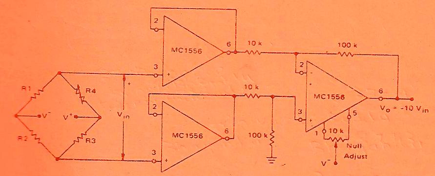
Rectifier Circuit - Other_circuit - Electrical_Equipment_Circuit

Analysis of Silicon Controlled Rectifier Circuit Diagram

ECE Mini Projects – 1000 Projects
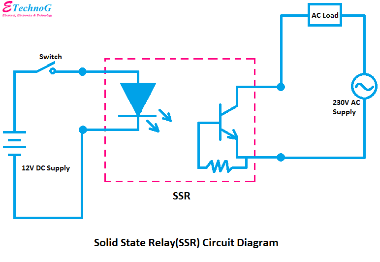
Solid State Relay(SSR) Circuit Diagram Explained - ETechnoG

12v 3 Phase Motorcycle Regulator/rectifier Circuit Wiring Diagram